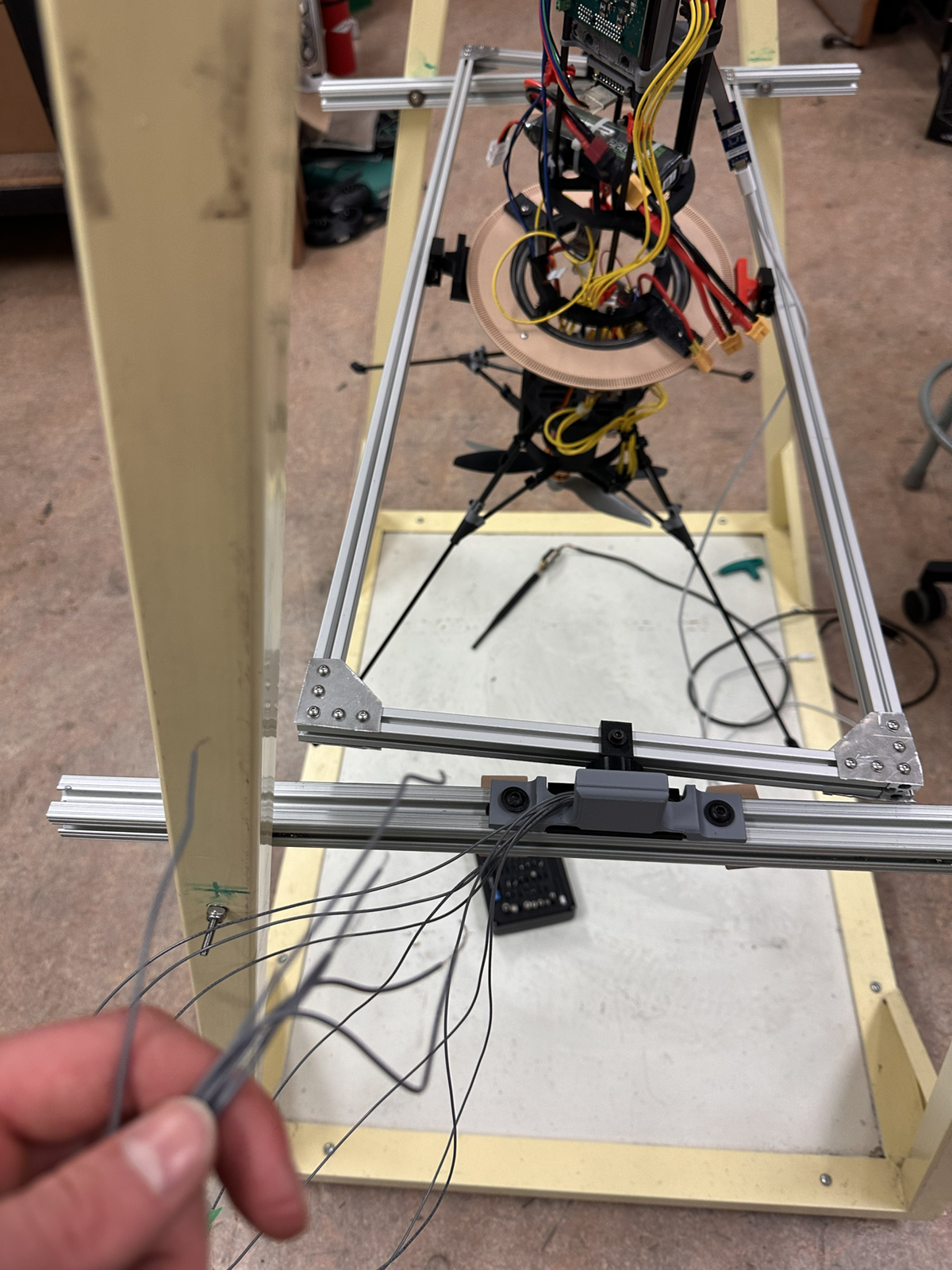
What I Did
I designed and helped build a 3-DOF gimbal stand that lets the rocket team mount a TVC test article, measure angular motion, and run controlled experiments on the bench.
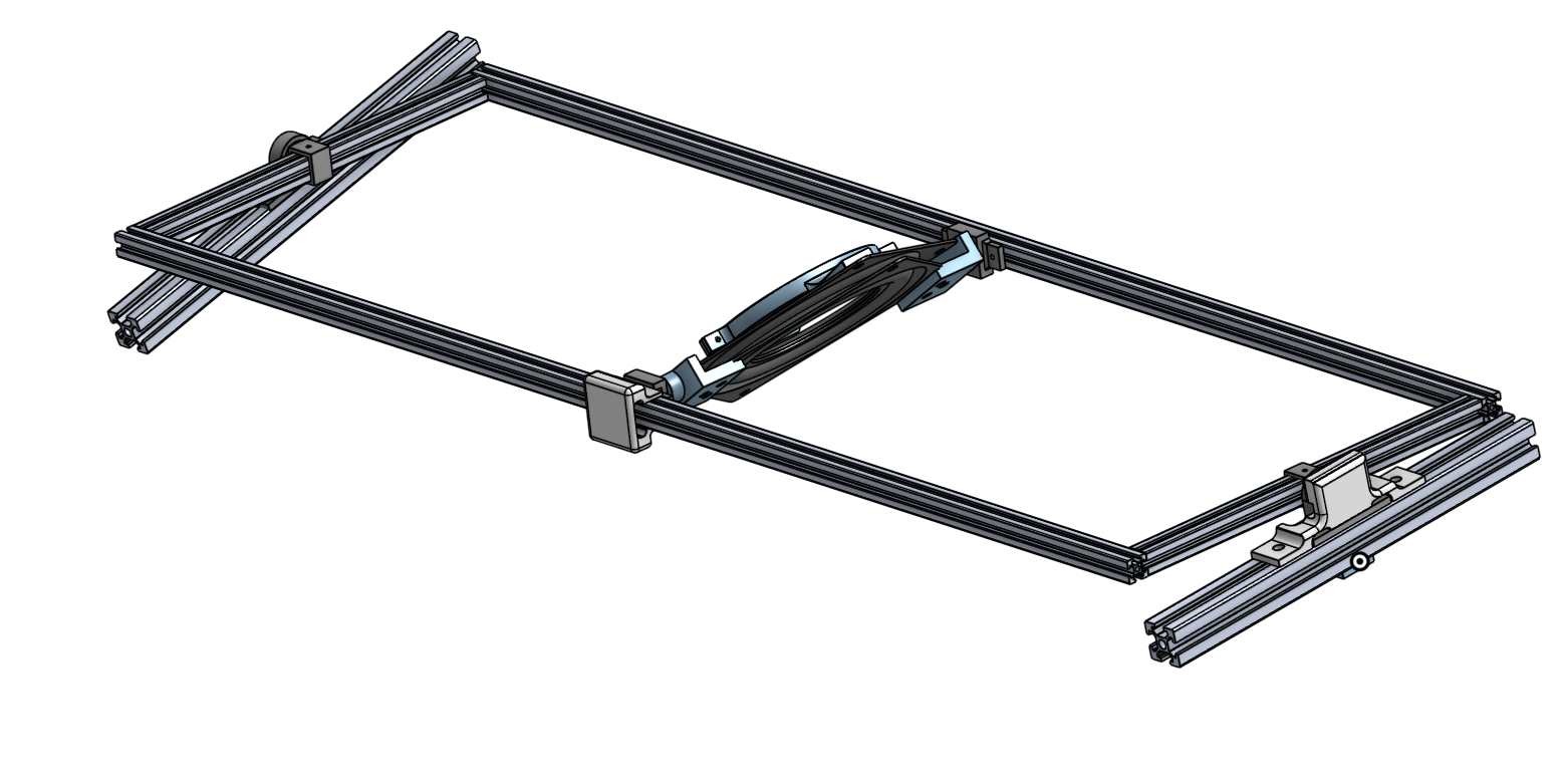
A test fixture for validating a thrust vector control gimbal before flight hardware integration, built around a rigid aluminum extrusion frame, a suspended vehicle assembly, and magnetic encoder feedback.
I designed and helped build a 3-DOF gimbal stand that lets the rocket team mount a TVC test article, measure angular motion, and run controlled experiments on the bench.
The team needed a controlled way to tune PID behavior and verify gimbal response while reducing reliance on full-system testing and limiting exposure of flight hardware during early iteration.
I balanced frame stiffness, access for wiring and electronics, encoder placement, and manufacturable brackets so the stand could be assembled, adjusted, and used repeatedly during controls testing.
Thrust vector control bench-test fixture
Drag to rotate the Onshape-exported CAD assembly. Scroll or pinch to zoom.
The stand supports physical PID tuning by giving the gimbal room to move across three rotational degrees of freedom while keeping the test setup inspectable. Magnetic encoders provide position feedback for comparing commanded motion against measured response.
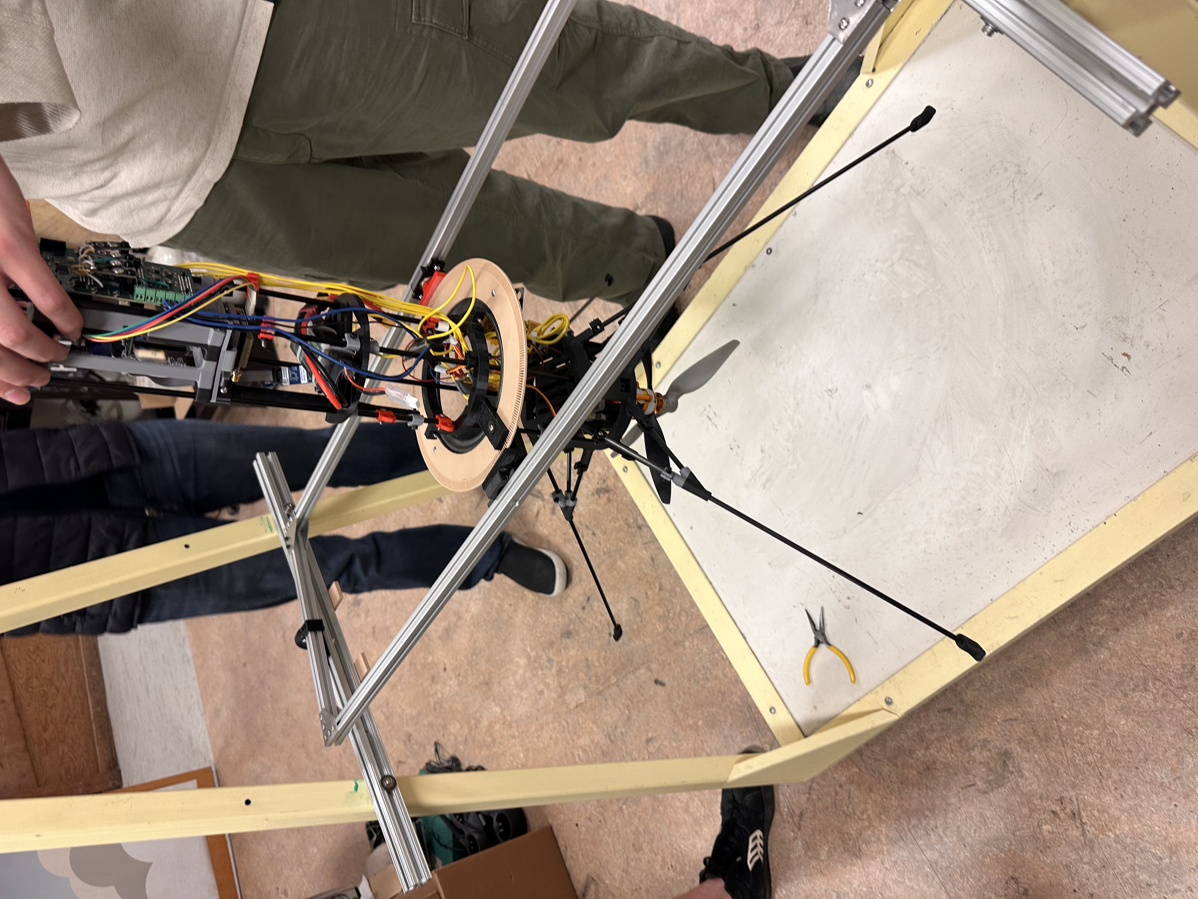
Stand after soldering outermost encoder. The bracket holds the sensor in a repeatable position on the frame while the wiring routes back toward the electronics stack, giving the controls team clean angular feedback during bench testing.